Understanding OBASHI Elements
Introduction
This article serves as a direct introduction to a core concept of OBASHI, Elements.
Elements are the key building blocks of any OBASHI diagram. Elements are placed into the OBASHI layers, and connections and dependencies are drawn between them.
An element is often illustrated as a simple rectangle. The length of the rectangle can vary depending on the scope of its relationship with supporting or supported elements. Each OBASHI Layer has a colour associated with it.
Elements within these layers default to the layer colour, however they can be customised to suit business requirements.
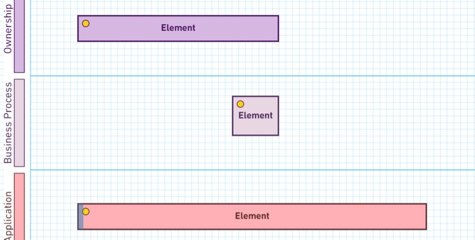
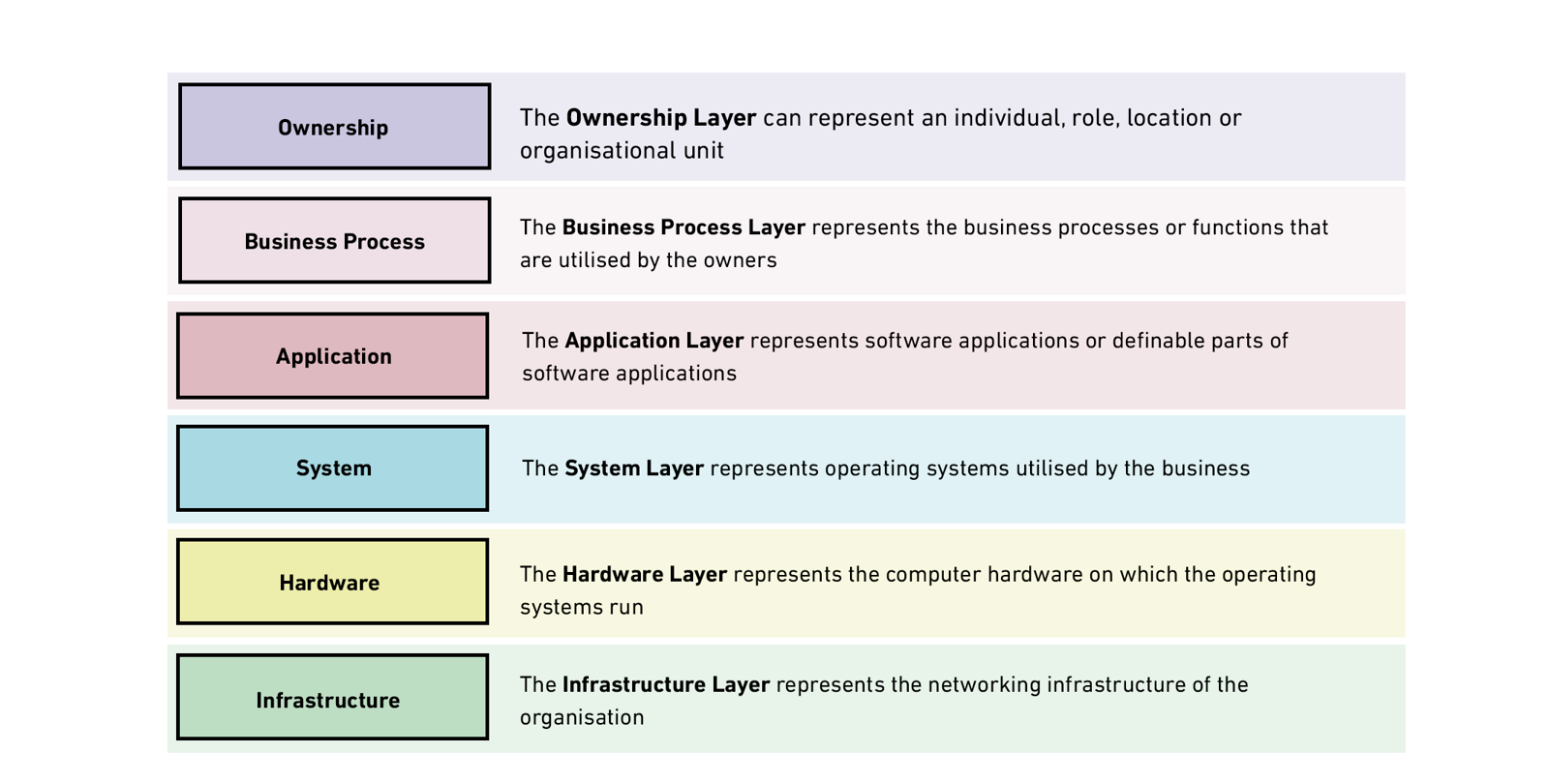
Layers
Each OBASHI Element is placed in its respective layer with each Element positioned above other Elements they own or utilise. Elements can also be placed hierarchically within a single layer to highlight reporting structures, smaller tasks and workflows, or sub-applications.
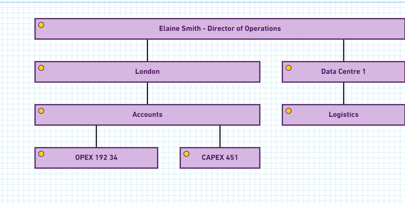
Element Hierarchies
Elements can be placed directly above and below each other to create hierarchies. This enables OBASHI models to be created at a high-level, but with more granular detail added as needed.
In the Ownership layer, hierarchies can be used to depict reporting structures. A high-level Business Process can be broken down into smaller sub-processes. Large applications can be sub-divided to show specific software functionality or the modules which comprise the application.
Multiple Instances
Multiple instances of the same element can reside on an OBASHI Diagram. There are many reasons why this modeling technique is applied.
Sometimes, repeating the same element on a Business & IT diagram can aid clarity, or it can allow the routing of connections to be simplified.
On other occasions, it can be used to enhance the visual impact of a B&IT, or can enable further context to be added to a proposed operational change.
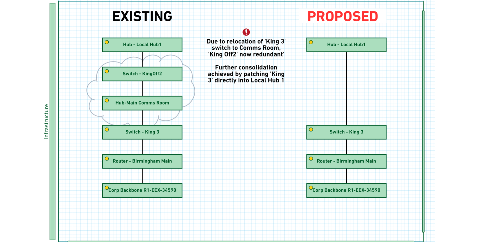
In the example below, multiple instances of the same element are placed side by side to show the current and proposed states. The redundant elements have been clouded up, and text has been added to provide more context.
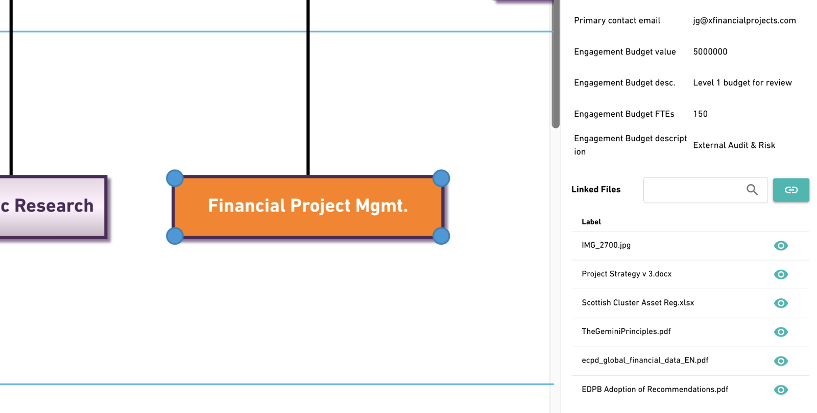
More than a Pretty Picture
Behind each element, you can add many types of data through custom fields as well as attach documentation. For example, these fields could include:
- Technical Specifications
- Risk Metrics
- Financial Information
- Process and Compliance Documentation